Reverse Camera Connection Guide
Ensure OEM menu and IDCORE interface menu displays/operates correctly before installing any aftermarket camera.
Vehicles with Automatic transmission*
* Exceptions – automatic transmission for IDC-B8MMIC (A4/A5 with MMI Basic, A6 C6 with MMI basic), IDC-MMI2G for all car models, IDC-D5C (2015-2016 XE/2015-2016 Discovery Sport/F-Type), IDC-ICTP8, IDC-ASTWF, IDC-ASTVL doesn’t apply to the automatic transmission guide. Refer to the manual transmission section below. BMW vehicles certain car models may not support any aftermarket cameras, provide the 17 digit VIN to check with us before camera installation.
Step 1 Settings
Dip switch 8-OFF to switch on aftermarket camera channel. Long press red reset button for 3 seconds to register the new dip setting.
Dip switch 4-ON to switch off guidance lines inbuilt in IDCORE interfaces.
Camera supported – NTSC and our cameras.
Step 2 Wiring connections
Turn car ignition ON, and select reverse gear. If the display changes to a black screen or a flashing black/white screen when in reverse, then wire camera as follows and rear view image should show. If the display doesn’t change and stays on IDCORE menu/Apple CarPlay/Android Auto menu, please follow the manual transmission section below for settings and wiring connections.
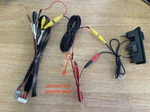
RED R.Rear 12v connects to power aftermarket camera
Plug camera video composite yellow connector into yellow ‘Rear video‘ composite video connector
Vehicles with Manual transmission*
*Exceptions – manual vehicles for IDC-D5C (2015-2016 XE/2015-2016 Discovery Sport) usually apply to the automatic transmission guide above. BMW vehicles certain car models may not support any aftermarket cameras, provide the 17 digit VIN to check with us before camera installation.
Step 1 Settings
Dip switch 4-ON and 8-OFF to switch on aftermarket camera channel. Long press red reset button for 3 seconds to register the new dip setting.
Camera supported – NTSC and our cameras.
Our camera settings –
If a white wire is on the camera, cut the white wire to enable guidance lines.
If a blue wire is on the camera, cut the blue wire to switch between front view camera and rear view camera.
Step 2 Wiring connections
Turn car ignition ON, and select reverse gear. If the display changes to a black screen or a flashing black/white screen when in reverse, then follow the automatic transmission guide above for settings and wiring connections.
- Orange wire marked REAR-C (Camera trigger wire) – Connect the camera trigger wire to vehicle reverse bulb positive wire. The reverse bulb positive wire is car dependant, please
refer to factory wiring diagram or use a multimeter to check the power source. Please note, the reverse light positive needs to output a minimum of 10.3v during reverse to provide sufficient power to trigger the camera mode to display.
Select reverse gear, if the display changes to a black screen or a flashing black/white screen when in reverse, the connection of trigger wire is successful and proceed to the next connection. If not, double check the power source for the trigger wire and the settings in step 1.
- Camera power wire – connect camera power wire to the same reverse bulb positive wire which connected to the orange trigger wire.
Camera video composite – connect to the yellow ‘Rear video‘ composite video connector.
Select reverse gear, instead of the black screen or a flashing black/white screen, it should display the camera image. Start the engine, if the camera image displays fine with the engine on as well as the engine off, wiring connection is completed. If the camera image is flickering, then connection of a relay is required to regulate power to the camera. If so, disconnect the connections above and follow the relay guide below.
- Relay guide – specification 5 pin, 12V, 40A
Pin 30 on relay connects to constant 12v power (car’s battery or fuse box)
Pin 85 on relay connects to a ground point on the car
Pin 86 on relay connects to cars reverse light positive identified previously
Pin 87 on relay connects to an inline 5A fuse (this step is important and if not done, it can damage the camera). The other end of the 5A fuse connects to the camera power and orange wire.
Pin 87A on relay – not used.
Then select reverse gear, the camera image should be steady when engine on and off. If flickering still , double check the relay connections.
Troubleshooting
- If it displays a black or black/white flashing screen in reverse, try plugging into the other yellow composite connector in case the rear view port and front view port are mislabelled.
- If all steps have been followed carefully but no camera image appears, it could be the camera used is not compatible. All of our cameras are tested with our products and we recommend using our cameras to eliminate this factor.

